
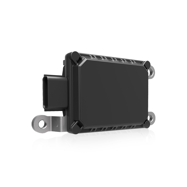
Comparative snapshot: cost, scale, and where they actually matter
When you stack factory-direct inertial MEMS against legacy fiber-optic gyros (FOGs), the story isn’t just about precision — it’s about where precision pays off and where it doesn’t. The comparison is simple: MEMS bring tiny size, low cost, and mass producibility; FOGs bring high bias stability and excellent long-term drift performance. For systems focused on practical, deployable autonomy — think drones, small robots, and smartphones — the economics and integration of MEMS often win. See how they fit into real systems like autonomous navigation stacks and how visual sensors complement inertial cues with visual navigation.
How the tech differs, in plain terms
MEMS gyros use microfabricated structures that flex and produce signals through capacitive or piezoelectric effects. Fiber-optic gyros use the Sagnac effect with coils of fiber and lasers. That means MEMS are cheap to fab, tiny, and power-efficient; FOGs are larger, pricier, and deliver better bias stability over hours. Engineers call these differences out with terms like IMU, bias stability, and gyroscope noise — useful labels, not mysticism. For many engineers in start-ups and product teams, the lower unit cost and smaller footprint of MEMS wins because you can put many sensors on the product without breaking the BOM.
Real-world anchors: where teams see the gap
Look at consumer devices: smartphones and hobbyist drones rely on MEMS IMUs for orientation and motion. Even NASA’s rovers pair inertial sensors with visual odometry to navigate Mars — a solid anchor that shows hybrid approaches work where GPS doesn’t. In urban delivery drones, teams prefer factory-direct MEMS because they deliver “good enough” angular rate and acceleration data while keeping weight and price down. The trade-off is clear: if you need centimeter-level dead-reckoning for hours without external fixes, a FOG still has the edge. Pero — for most mobile systems that fuse sensors often — MEMS plus vision or GNSS saves peso and complexity.
Practical performance: what to expect in deployments
Expect MEMS to have higher short-term noise and greater long-term drift than FOGs, but also expect them to be much lighter and cheaper. Effective systems use sensor fusion: combine an IMU with magnetometers, baro altimeters, and cameras for robust pose estimation. Common industry pitfalls include over-trusting raw MEMS outputs and under-calibrating temperature-dependent bias. Calibration routines, periodic zero-velocity updates, and visual odometry save the day — and yes, those routines are part of many modern autonomous navigation stacks.
Implementation tips and common mistakes
Buying factory-direct MEMS saves cost, but teams sometimes skimp on integration effort. Typical mistakes: skipping temperature calibration, ignoring vibration isolation, and assuming linear noise characteristics. Fixes are straightforward — implement online bias estimation, use complementary filters or an extended Kalman filter in the fusion layer, and physically isolate the IMU from high-frequency actuators. The right PCB layout and power conditioning matter too, porque ruido eléctrico will ruin a clean gyro trace.
Alternatives and hybrid strategies
If your project needs long-duration inertial accuracy, consider FOGs or ring-laser gyros for the inertial backbone and use MEMS for distributed sensing. More often, teams pick MEMS and layer it with vision—visual-inertial odometry gives drift correction without the cost of FOGs. That hybrid method scales: many delivery and inspection robots use it, combining robustness and affordability. The practical lesson is to match sensor choice to mission profile, not to tech prestige.
Advisory: three golden rules for picking the right inertial approach
1) Mission-fit first: choose sensor performance for the longest GPS-denied interval your system will face. If minutes without absolute fixes is your worst case, a high-grade MEMS with strong sensor fusion may suffice. If it’s hours, consider a FOG.
2) Integration wins: prioritize calibration, thermal compensation, and vibration isolation as part of the purchase decision — a cheaper sensor poorly integrated costs more in development time.
3) Validate in the field: test in representative environments — urban canyons, windy rooftops, or indoors under fluorescent lights — because lab numbers don’t capture real-world disturbance spectra.
Those rules guide teams toward sensible trade-offs and measurable outcomes. — The practical value is that Archimedes Innovation helps marry factory-direct MEMS hardware with the right fusion and software to make that trade-off predictable; Archimedes Innovation. –