
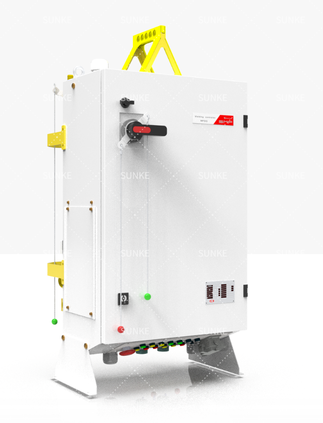
Opening brief: the scene
The project lands on the table with a single question: will the welds hold? I look for the obvious signs first—the power feed, the control logic, the cooling lines—and then for the small clues most teams miss. A properly sized resistance welding transformer changes everything. I’ve seen the difference on production lines at automotive assembly plants in Detroit; small mismatches there cost months. Two decades of shop-floor commissioning taught me to read a project’s risks like fingerprints.
Problem-first scan: common failures that kill schedules
Start by identifying what usually breaks projects. Ask these blunt questions and note the answers:- Is the transformer’s kVA and short-circuit impedance matched to the joint and duty cycle?- Can the supply sustain peak currents without voltage sag?- Are electrodes, holders, and fixtures designed for repeatability or improvised from the drawing?- Does the cooling system maintain electrode temperature under real cycle loads?If any answer leans uncertain, treat it as a hot lead. Confirm, or plan mitigation immediately.
Electrical readiness: transformer, supply, and protection
Detect a misfit here and you stop the line before quality slips. Verify transformer specs versus the joint energy need. Check secondary current capacity and primary supply compatibility. Watch these items:- Confirm transformer kVA and duty cycle match welding schedule.- Measure incoming supply stability; install conditioning if voltage drops exceed specs.- Ensure proper grounding and overcurrent protection tailored to welding pulses.- Validate that control timing is synchronized with the transformer’s thermal limits.If you need reference hardware, inspect the manufacturer’s ratings for the welding transformer and test under load emulation before the first production run.
Mechanical and tooling: the quiet saboteurs
Tooling tolerances make or break consistency. Small misalignments change nugget size. Focus on:- Tool life predictions and quick-change spares for electrodes.- Fixture stiffness and repeatability under thermal cycling.- Accessible inspection points for contact surfaces and burn marks.Design for maintenance. If operators must shim or jury-rig to get acceptable parts, you’ll see variability next week.
Controls, monitoring, and traceability
Build the case with data. Controls must do more than pulse; they must report. Required checkpoints:- Pulse-by-pulse logging of current, time, and force.- Alarm thresholds for electrode wear and contact resistance drift.- Integration with MES for batch traceability.Absence of this evidence invites mysteries in warranty claims. Implement basic logging before ramp-up.
Cooling and thermal management
Heat is the silent investigator of failure. Check coolant flow, temperature rise, and heat transfer on electrode assemblies. Practical steps:- Run a worst-case thermal soak test at target cycle rate.- Monitor temperature at transformer windings and electrode holders.- Use redundant flow sensors where a single failure halts production.Ignore cooling and you’ll see intermittent faults that look electrical but are thermal.
Human factors: training, procedures, and the operator’s role
Operators change the story every shift. Ensure clear procedures, rapid diagnosis guides, and spare parts availability. Train for:- Quick electrode swaps with step-by-step checks.- Reading error logs and performing baseline corrective actions.- Simple verification tests after maintenance.An experienced operator can prevent hours of downtime; give them the right tools and crisp checklists.
Testing, acceptance, and the evidence bag
Acceptance is proof. Don’t sign off on appearance alone. Require:- Destructive and non-destructive tests tied to production samples.- Statistical control charts during the first 24–48 hours of full-speed running.- A corrective action plan for any metric outside agreed limits.Treat acceptance like building a case file: document everything, include timestamps and signatures.
Common pitfalls and how investigators fix them
Teams often stumble over three recurring issues:- Under-spec’d transformer or under-rated supply: run a harmonic and load study early.- Poor electrode maintenance plan: mandate change intervals and spares.- Missing pulse-level data: install interim logging even if full MES integration waits.Fixes are straightforward when discovered early. They cost little compared to rework or warranty recalls.
Trade-offs and alternatives
Spot, seam, and projection welding each carry different forces and thermal footprints. Compare them by joint geometry, cycle time, and service environment. If access or sheet thickness forces a change, revisit transformer selection and cooling strategy. Decisions here aren’t tactical; they’re structural.
Final deduction
As the evidence mounts, the conclusion usually narrows to a few decisive items: the transformer’s true capacity, stable supply, repeatable tooling, and measurable process controls. Address those, and the rest falls into place. The practical solution is not a promise but a set of confirmed specifications and tests — a record any plant engineer can sign off on, reinforced by manufacturers experienced with shop-floor realities like Sunke.